· FabLab Westharima Team · Electronics · 5 min read
[Arduino] Otto DIY Original Robot Creation
Based on open-source bipedal robot Otto DIY, created an original robot. Work record utilizing Arduino programming and 3D printing.
At the end of 2020, the cute movements of OTTO DIY (bipedal walking robot) became a topic in our household, and we made one using open data from the official site. For my study, instead of purchasing the official site’s ‘Otto DIY builder kit’, we purchased each part ourselves and also did 3D print output of body and soldering of electronic parts. I’ve summarized the experience as a memo.
※This article is a memo from making OTTO DIY (Starter set.V9) at the end of 2020, so it may differ from the latest version on the official site. Please check the latest information on the official site when making.
Obtaining Manual and 3D Files
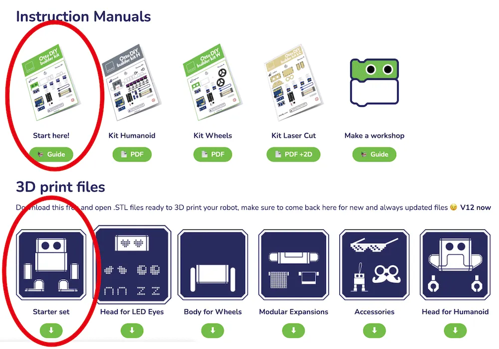
First, from the official site ‘OTTO DIY Academy’, we obtained
The simplest manual ‘Start here!’ and body 3D print file ‘Starter set.V9’ (※circled marks)
Equipment & Tools
※This article was created in 2020. The equipment currently used at FabLab may differ.
- 3D Printer
- Soldering iron
- Wiring tools
For currently available equipment, please check the Equipment List.
Materials
We prepared the following materials based on official site recommendations, etc.
1 x 8mm lock switch
1 x Battery box (4 AA batteries, 2×2 type)
4 x AA alkaline batteries
Tools
File (for deburring after 3D printer output)
USB cable Type A-miniB (for Arduino writing)
Complete set of soldering tools
Preliminary Preparation
Next, we did preliminary preparation before assembly.
※Note: If purchasing ‘Otto DIY builder kit’ from official site, body and pre-soldered parts are included, so this preliminary preparation is unnecessary.
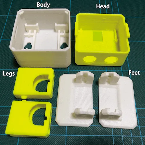
STEP 1: 3D Print Body
※Obtained 3D print filesV.9 from official site ‘OTTO DIY Academy’ and output with 3D printer.
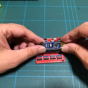
STEP 2: Soldering
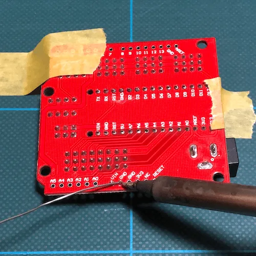
Battery 2 pins of Arduino Nano I/O expansion shield (board)
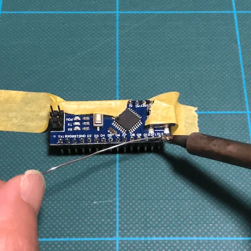
Arduino pins
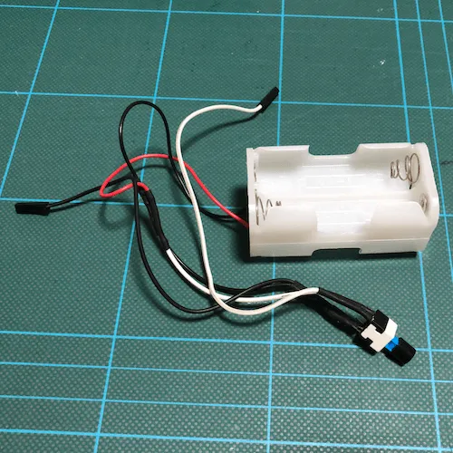
Switch and battery box connection part
OTTO Assembly
With all parts ready, we started OTTO assembly referring to ‘Otto DIY builder kit assembly manual.Version10’.
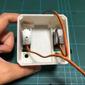
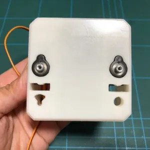
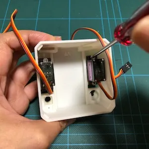
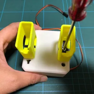
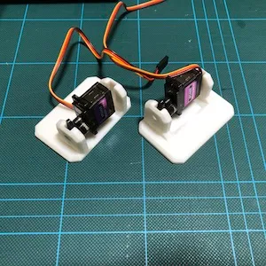
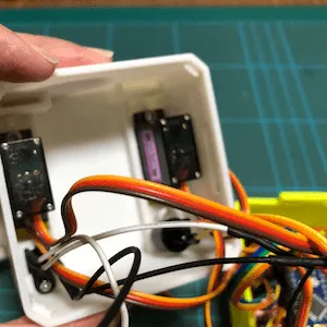
STEP 3: Attach servo to body and fix
Attach servo to body ×2, fix with longer screws ×4
※Be careful of direction. Attached where bottom body hole shape matches servo shape.
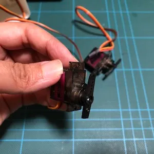
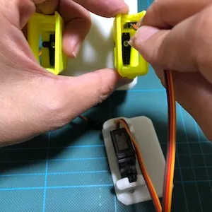
STEP 4: Attach servo horn to LEG
Cut servo horn and attach to LEG ×2
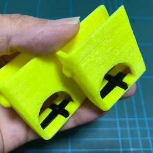
STEP 5: Attach servo to LEG
Attach servo to LEG ×2
※Before attaching, set servo to middle position of range of motion (180 degrees).
※Servo gear chips easily, so be careful when moving by hand. I broke one despite this and replaced it.
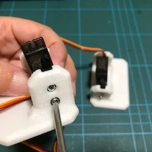
STEP 6: Fix with shorter screws
Fix with shorter screws ×2
STEP 7: Attach servo horn to servo
Cut servo horn and attach to servo ×2
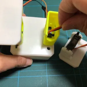
STEP 8: Attach servo to FOOT
Attach servo to FOOT ×2
※Before attaching, set servo to middle position of range of motion (180 degrees).
※Servo gear chips easily, so be careful when moving by hand.
STEP 9: Fix FOOT servo
Fix FOOT servo with short screws ×2 (top) and long screws ×2 (bottom)
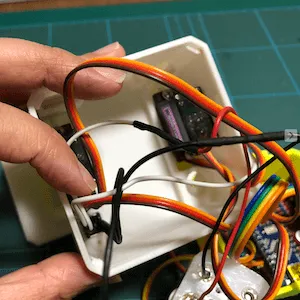
STEP 10: Pass wiring through hole
Pass both FOOT servo wiring through body holes
※Body hole is very narrow, so it doesn’t pass easily. Struggled with this.
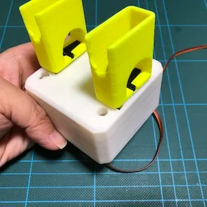
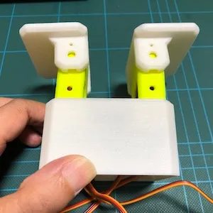
STEP 11: Leg assembly mostly complete
STEP 12: Fix LEG servo
Fix servo inside LEG with long screws ×2
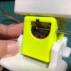
This work was quite difficult. Screwdriver was hard to maneuver, and working while avoiding servo wiring, screws kept rolling away. Difficult work even for adults, so children will struggle even more.
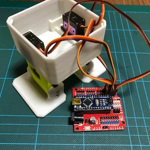
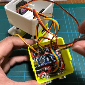
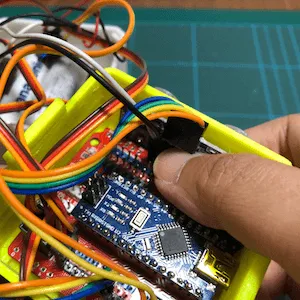
STEP 13: Attach Arduino to board
Attach Arduino to Arduino Nano I/O expansion shield (board)
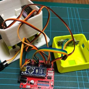
STEP 14: Insert connectors into board
Insert connectors coming from legs into board ×4
Insert connectors coming from legs into board. Referred to official site wiring diagram for connector insertion positions. It was unclear which connector was LEG or FOOT, right or left, so inserted pins while making various guesses like “maybe shorter wiring is FOOT?”. (※If inserted incorrectly here, foot movement will be strange after completion.)
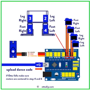
Official site leg wiring diagram
STEP 15: Attach sensor to head
Attach sensor to head
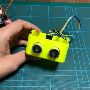
STEP 16: Wire sensor and buzzer
Insert sensor and buzzer pins into board
Inserted pins referring to official site wiring diagram.
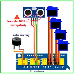
Official site sensor/buzzer wiring diagram
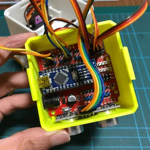
STEP 17: Attach board to head and fix
Attach board to head while being careful of direction, fix with long screws ×2
※Head size and board are almost same size, so this attachment was very difficult.
STEP 18: Attach switch to body and fix
Attach switch to body, secure with servo horn, fix with long screw ×1
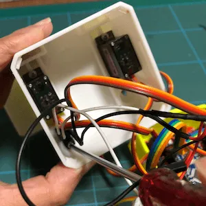
STEP 19: Wire battery box
Insert battery box wiring pins into board
※Connected carefully with sufficient attention as connecting backwards can cause short circuit or heating.
※This time used alkaline batteries, so referred to alkaline battery wiring diagram.
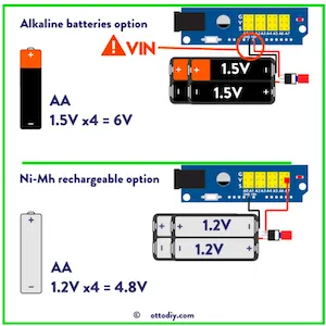
Official site battery pin wiring diagram
STEP 20: Attach buzzer
Attach buzzer
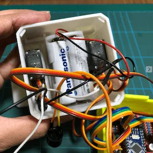
STEP 21: Put batteries in body
Put batteries in battery BOX and put battery box in body
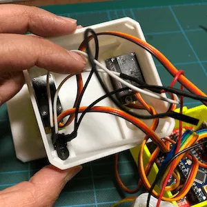
STEP 22: Close head and body
Pack wiring and parts into head and body and close.
Carefully avoiding pinching wiring, closed head until it fit into left and right tabs of head.
Since wiring and parts were packed tightly, struggled with storage but managed to fit them.
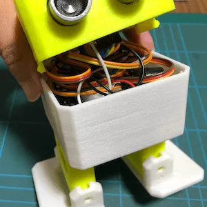
STEP 23: Complete!
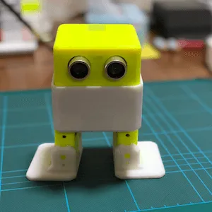
Summary and Impressions
If I, a beginner in electronics, had been alone, soldering would have been a bottleneck and I would have given up partway.
For those not familiar with electronics, recommend making OTTO together with someone familiar with electronics.
Servo gear chips easily, so be careful when moving by hand.
Official site ‘OTTO DIY Academy’ has no Japanese translation version, and the only option is to work hard at translation, which is a bit tough.
Official site said assembly takes 1 hour, but I needed 2-3 hours.
Addendum: 2021/11/9
After a long time, when I looked at official site ‘OTTO DIY Academy’, it had been version upped! Considering making the latest version soon. When I make it, I plan to post another article.