· FabLab Westharima Team · 3D Printer · 4 min read
First Attempt at Making Akabeko – Using Fusion360/3D Printer
3D printing akabeko (traditional Japanese toy) using Fusion360 form modeling. Complete guide from data creation to assembly and painting, including trial-and-error process and lessons learned.
I challenged myself to make an “akabeko” (a traditional Japanese bobblehead cow toy from Fukushima) using a 3D printer for the first time. To preserve the process, I’m documenting the “how-to,” “materials needed,” and “what I learned” as a reference for myself (details below).
Re-learning Fusion360 “Form Modeling”
When I tried to use Fusion360’s form modeling feature for the first time in six months, I couldn’t quite remember the operation flow or menu button locations. Even after I thought I understood it and started creating, I couldn’t achieve the ideal body shape, and while making minor adjustments, intersection errors occurred frequently (tears). Although I only output a few bodies, in Fusion360 it became a repetition of creating and deleting bodies.
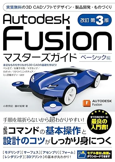
To create the body I wanted, I re-studied form modeling once again using “Autodesk Fusion Masters Guide Basic Edition 3rd Revised Edition”. I realized the importance of consciously and continuously using software and features multiple times. Ah, when will I graduate from this textbook…
Required Items and Materials
For 3D Printer Use
- 3D printer
- Computer
- 3D CAD software
- Slicer software
- Filament
For Making Akabeko
- Sandpaper
- File
- Pin vise
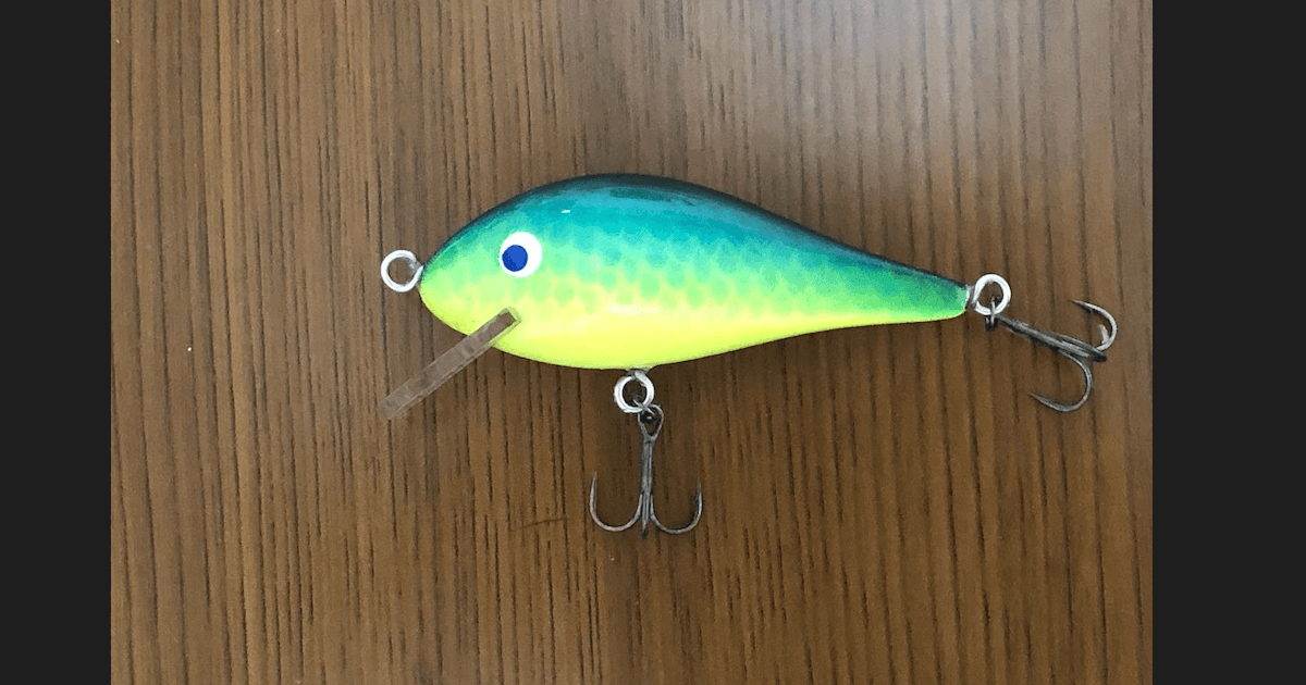
- Weight (any weight is OK, but I used several round fishing weights)
- Thread
- Super glue
- Posca markers
How to Make Akabeko - My Process
STEP 1: 3D Data Creation
Create data in 3D CAD software
*Software used: “Fusion360” *Among several prototypes, I’ll introduce the body creation process that worked best.
[Creating Body and Legs]
- First, create the base shape using “Create Form” → “Box”. *To create a symmetrical body, utilize the mirror function.
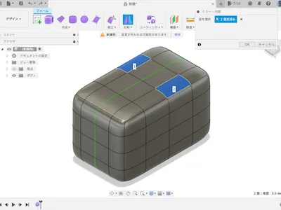 Utilize “Edit Form,” “Insert Edge,” “Subdivide,” etc. to create legs under the body.
 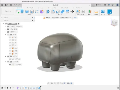 Repeat “Edit Form” to create rounded body and leg shapes.
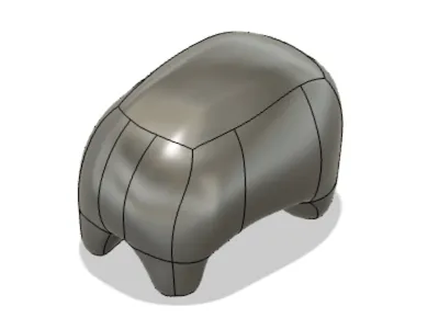
- Create internal structure Use “Shell” to hollow out the inside and create walls. (Reference: Create with a thickness that doesn’t cause errors.)
- Create two cylinders as new bodies for the neck and thread holes.
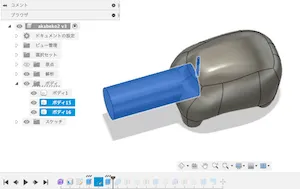
- Using the “Combine” function, cut out the “two cylinders” created in “3” from the body,
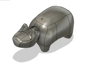
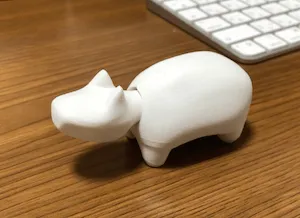
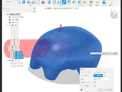 Body and legs shape completed
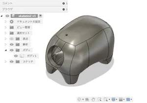
- Hide the body and legs, and start creating the head and neck body.
[Creating Head and Neck]
- First, create the base shape using “Create Form” → “Box”. *To create a symmetrical body, utilize the mirror function, then use “Edit Form,” “Insert Edge,” “Subdivide,” etc. (The neck is intentionally made longer. Plan to cut off unnecessary parts later)
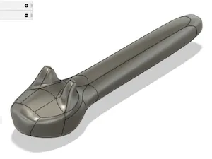
- Cut off unnecessary parts of the neck. *Utilize “Offset Plane” and “Extrude”.
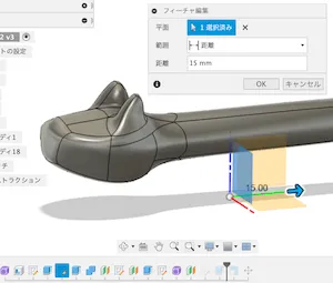
- Head and neck shape completed
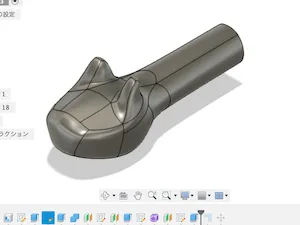
When I hollowed out the head and neck with “Shell,” the shape collapsed during 3D printer output, so I abandoned the shell approach. Instead, I decided to address this by “changing the infill values in the next slicer settings process.”
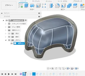
[Body Completed]
- Display both bodies and check & adjust the balance.
- If you want to change the body size, use the scale function.
STEP 2: STL File Export
Export file from 3D CAD software (STL format)
[In this case] In Fusion360 → “Utilities” → “Make” → “3D Print”, select each body and export in STL format. 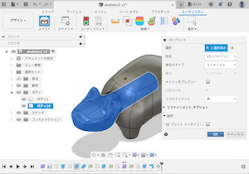
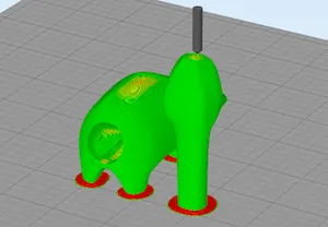
STEP 3: Slicing Process
Convert to data format for 3D printer output (using slicer software)
Software used: “Simplify3D” Based on lessons learned from test output, I added the following slicer settings and exported in gcode format.
[Head and neck orientation]… Changed to vertical [Additional feature - Skirt] … Red part in the diagram below. Set because the body peeled off the bed during test output. [Infill - Internal fill ratio] … Set to a small amount.
STEP 4: Load Data
Load slicer data into the 3D printer
STEP 5: Set Filament
Set material (filament) in the 3D printer
STEP 6: 3D Print Output
Output with 3D printer 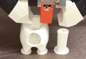
STEP 7: Remove Object
Remove the 3D printed object from the 3D printer
After 3D printer output, remove the 3D object after the bed has cooled down.
STEP 8: Post-processing
Remove supports and unnecessary parts (deburring, sanding, etc.)
This time, to thread the string and insert the weight, I also removed the infill inside the neck.
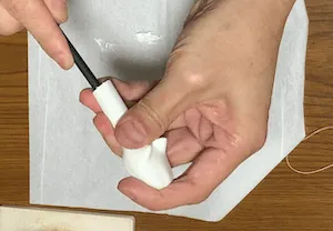
STEP 9: Assembly
Assembly
- Put the weight in the neck and decide where to hang the neck from the body with thread.
- Drill a hole in the neck with a pin vise and hang it from the body with thread.
- Check if the head moves nicely (*If the movement is not good, repeat steps 1-3.)
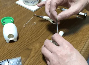
- Fix the weight and thread with super glue
- Assembly
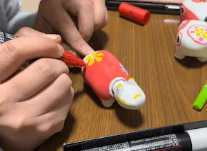
STEP 10: Painting
Painting
This time, painted with Posca markers
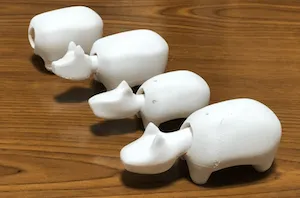
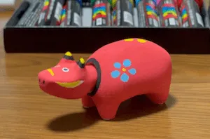
Completed!
Impressions
- When painting after assembly, the area around the neck was difficult to paint. I thought it would be safer to paint first and then assemble.
- I hadn’t used Fusion360’s “form modeling feature” for a while, and I struggled to remember the menu and button locations, among other things. I realized the importance of continuously using software and features.