Otto WHEEL FabLab Westharima Model Assembly Manual
Assembly instructions for the FabLab Westharima Model (Test Unit) of the wheel-type “Otto WHEEL”.
Parts
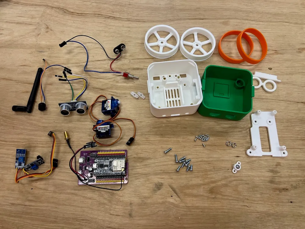
- 3D Printed Body Parts (head, body, wheels x2, mounts x2 types, glasses)
- 2x Silicone Bands
- 2x Servo Motors FS90R
- ESP32 Expansion Board + ESP32 DevKit
- 2x Line Tracking Sensors TCRT5000
- Ultrasonic Sensor RUS-04
- Switch
- Buzzer
- Jumper Wires
- Ball 8mm diameter
- Screws and Nuts
Sold Separately
Tools Needed
- File (for deburring 3D printed parts, if needed)
- USB Cable (for firmware upload)
- Precision Screwdriver
- Nippers
- Soldering Equipment
Wiring Precautions
- ⚠️ Carefully check the connection diagram and pay attention to orientation
- ⚠️ Wrong orientation can cause short circuits
- ⚠️ Pay special attention to VCC/GND wiring: Always confirm the orientation of positive (red) and negative (black)
- ⚠️ Keep wiring short and organized: Be careful not to tangle wires
- ⚠️ Turn off power before connecting: Always turn off power during wiring work
Assembly Tips
Please confirm and understand the following before assembly.
Avoid Over-tightening Screws
- Over-tightening can strip screw holes
- Over-tightening can damage 3D printed parts
- Tip: Hold the screwdriver without gripping too tightly, and tighten with moderate force
Pay Attention to Screwdriver Size
- There are 2 screw sizes. Use the appropriate screwdriver for each screw size
Check Wiring
- Especially for power connections, check the wiring diagram as reversing positive/negative can damage electronic components
Motor Left/Right
- If motor wiring is reversed left/right, forward/backward movement will be reversed. In that case, swap the wires to correct it
Connection Table
| Sensor/Motor | ESP32 Board Pin | Notes |
|---|---|---|
| Line Tracking Left (Analog) | 32 | Analog Input |
| Line Tracking Right (Analog) | 33 | Analog Input |
| Left Motor | 14 | PWM Output |
| Right Motor | 13 | PWM Output |
| Ultrasonic Sensor RGB | 18 | Digital Output |
| Ultrasonic Sensor Echo (io) | 19 | Digital Input |
| Buzzer | 25 | PWM Output |
Assembly Steps
1. Body Assembly
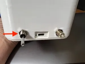
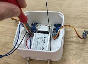
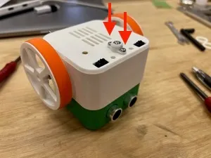
Antenna Installation x1
| Insert antenna into body (right side) hole | Secure with nut |
|---|---|
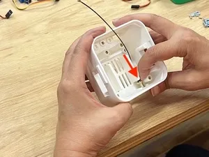 | 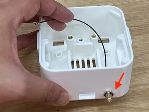 |
Switch Installation x1
Align the switch so the OFF side faces the bottom of the body
| Insert switch through body (left hole) | Secure with nut |
|---|---|
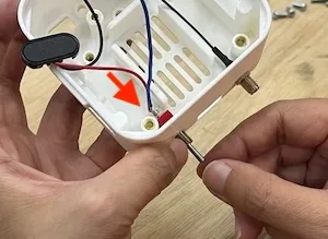 |  |
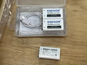
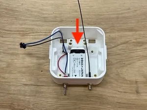
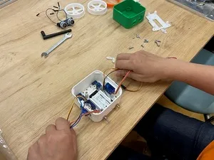
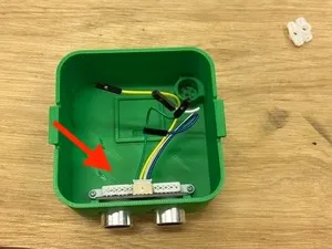
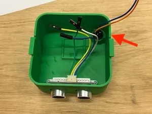
Connect Lithium-ion Battery (9V Rechargeable) to Wiring
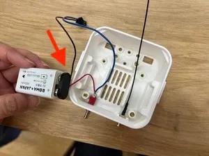
Insert Lithium-ion Battery into Body
⚠️ Be careful not to pinch wires!
Line Sensor Installation (Left/Right)
| Secure with screws (M3x8) | ⚠️ Position check: OK if line sensor is not skewed |
|---|---|
 | 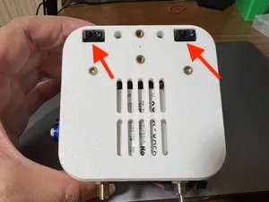 |
Servo Installation (Left/Right)
| Pass wiring through body hole | Secure with tapping screws (M2x6) ⚠️ Watch servo orientation |
|---|---|
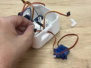 | 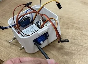 |
Mount Installation
| Move wiring to both sides | Screw mount in place (M3x8) |
|---|---|
 | 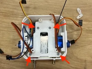 |
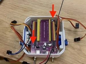
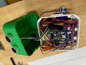
ESP32 Expansion Board Installation
- ⚠️ Be careful not to pinch wires!
- Screw in 2 diagonal positions (M3x12)
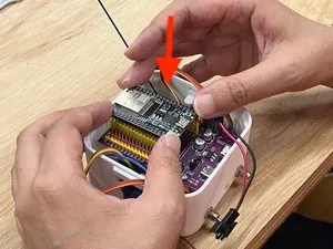
ESP32 DevKit Installation
⚠️ Align the expansion board connector with ESP32 DevKit connector and push straight down. (Don’t insert at an angle)
Wiring
| Sensor Signal | ESP32 Board Pin |
|---|---|
| Line Tracking Left (Analog) | 32 |
| Line Tracking Right (Analog) | 33 |
| Left Motor | 14 |
| Right Motor | 13 |
VCC/GND Wiring
⚠️ Wrong orientation can cause short circuits! Always confirm the orientation of positive (red) and negative (black).
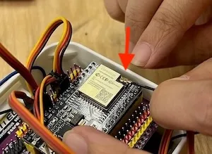
Antenna Installation
Attach antenna to “Wifi Antenna Connector” on the front of ESP32 DevKit (align position carefully and push in firmly with fingernail)
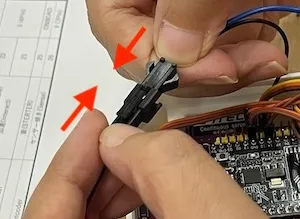
Battery Wiring
Battery connection terminal on switch wiring
2. Head Assembly
Ultrasonic Sensor Installation
- Insert ultrasonic sensor from inside the head
- Place mount and screw in (Tapping screws M2x6 x2)
Buzzer Installation
Wiring: Each Sensor Signal
Connect with the following pin numbers
| Sensor | ESP32 Board Pin |
|---|---|
| Ultrasonic Sensor RGB | 18 |
| Ultrasonic Sensor Echo (io) | 19 |
| Buzzer | 25 |
Wiring: Each Sensor VCC/GND
⚠️ Wrong orientation can cause short circuits!
Combining Head and Body
- Align head and body orientation
- ⚠️ Be careful not to pinch wires
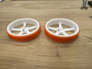
3. Wheel Assembly
Servo Horn Preparation
Slightly enlarge 2 holes so tapping screws M2x6 can fit (to prevent servo horn damage)
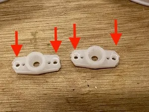
Screw Servo Horn to Wheel
Tapping screws M2x6, 2 each for left and right
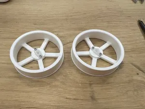
Silicone Rubber Installation
Screw Assembled Wheels (Left/Right) to Servos
Tapping screws M2x6 (1 each for left and right)
| Screw position | Photo after screwing |
|---|---|
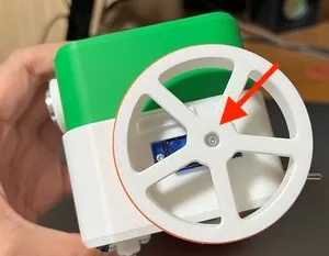 |  |
4. Ball Installation
| 1. Insert ball into mount | 2. Screw to body (M3x8 x2) |
|---|---|
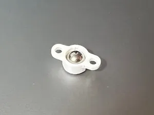 |  |
5. Antenna Installation
| 1. Antenna installation | 2. Raise antenna |
|---|---|
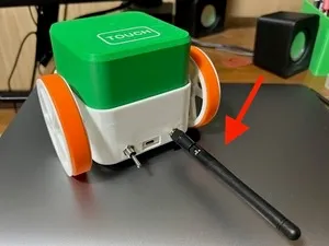 | 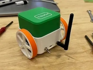 |
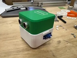
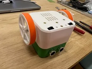
6. Completion & Operation Check
Insert battery into battery holder and turn on power switch.
If a program has been uploaded beforehand, the robot will start moving. If programming is needed, connect to PC and upload program using dedicated software (Otto Blockly, etc.).