Otto DIY - Humanoid Making Manual
The Beginning of Otto DIY
Otto DIY was born as an open-source bipedal walking robot that anyone can easily assemble. By utilizing 3D printed parts, commercially available electronic components, and an Arduino-compatible microcontroller, it provides a relatively low-cost and highly customizable platform. Founder Camilo Parra Palacio started the project around 2016 with the aim of giving children and beginners the joy of learning and creating through robots. Since then, many engineers, educators, and creators have joined the community, sharing information and improvements across borders.

Features of Otto DIY
- Open Source: 3D data, circuit diagrams, and programs are publicly available, and users worldwide can freely modify and redistribute them.
- Learning Platform: Adopted as teaching material for children’s workshops and STEM education, allowing practical learning of robotics and programming basics.
- Community Contribution: Members from around the world share code and design upgrades, with extensive documentation in multiple languages.
- Easy Modularity: Expandable with sensors, LEDs, speakers, etc. Enjoy various arrangements such as moving with motion sensors or dancing to music.
FabLab Westharima Model
We’ve improved the difficult-to-assemble parts of “Otto DIY - Humanoid” at FabLab Westharima. The assembly procedure for the FabLab Westharima version is as follows.
[0. Preparation] Upload 180° Servo “Servo Centering Code” to Microcontroller
0: Software Preparation:
For Windows: Install Otto blockly Windows software (first time only)

- Open Ottoblockly
- Add “Pin Settings” to the sample code “servo centering” (see figure below)
- Connect to microcontroller port > Upload Note:
- Current setup: Microcontroller: Nano / USB Port: COM3
- If writing to Nano fails, try changing to Nano Old
- Port numbers change depending on the computer and USB port used, so don’t worry about the number itself
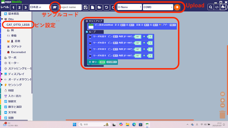
- After upload is complete, servo centering will activate when 5V power is supplied to the microcontroller
Now, let’s start assembly.
Leg Assembly
Attach Servos x2
- Servo 2: Leg left
- Servo 3: Leg right
- Screws x4
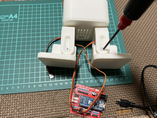
Servo Centering
- Connect servos to pins 2 and 3 of the microcontroller and connect power (USB cable). Look carefully at the connection diagram and pay attention to the connector orientation.
| Parts | Connection Diagram |
|---|---|
 |  |
Attach Legs
- Place the leg with four holes visible and press in the servo horn
| Parts | Attention to Orientation |
|---|---|
 |  |
Servo Horn Screw Fixing
- Be sure to disconnect the USB cable from the microcontroller before screwing the servo horn ※ Keep the servo unpowered during screwing (to prevent servo damage)
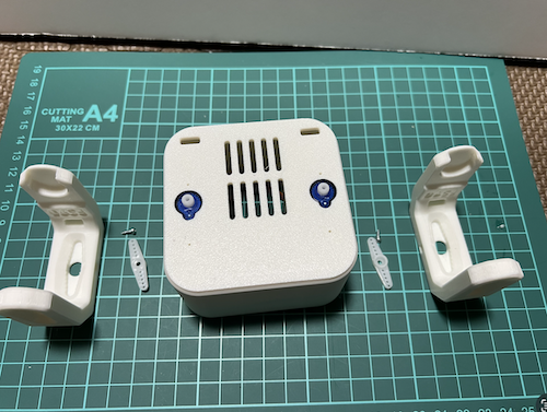
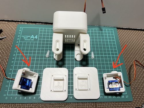
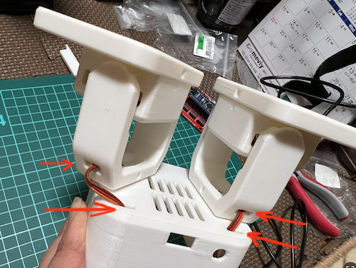
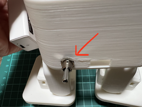
Foot Assembly
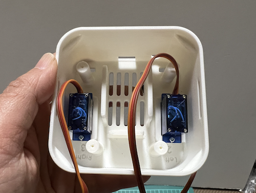
Attach Servos x2
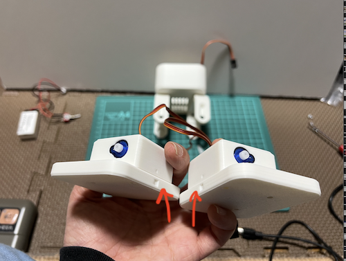
- Insert servos into the parts indicated by red arrows
- Servo 4: Foot left
- Servo 5: Foot right
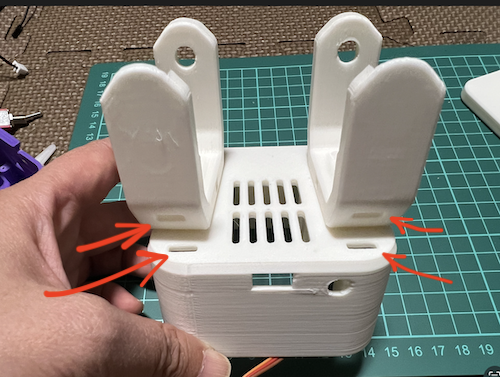
- Close the lid as shown in the photo and screw x8 Pay attention to the red arrow area. Match RIGHT INSIDE with LEFT INSIDE
- Slide the foot and insert the left and right ANKLEs, paying attention to the red circle area (D-cut orientation)
| Parts | Attention to Orientation |
|---|---|
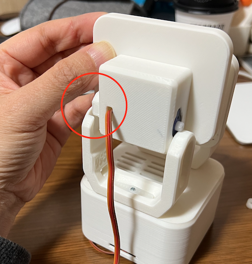 |  |
Servo Centering
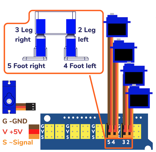
- Connect servos to pins 4 and 5 of the microcontroller and connect power (USB cable). Look carefully at the connection diagram and pay attention to the connector orientation.
| Parts | Connection Diagram |
|---|---|
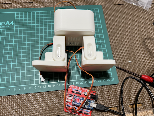 | |
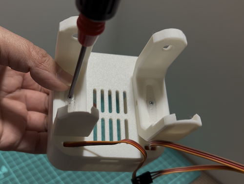
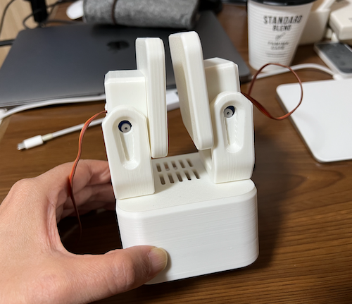
Press in Servo Horn
Servo Horn Screw Fixing
- Be sure to disconnect the USB cable from the microcontroller before screwing the servo horn ※ Keep the servo unpowered during screwing (to prevent servo damage)
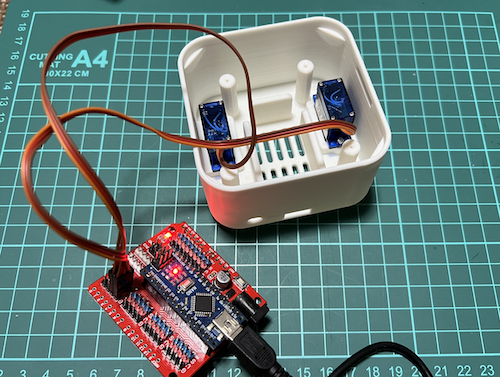
Foot Servo Wiring
- Pass the foot servo wiring x2 through the leg holes and body holes respectively
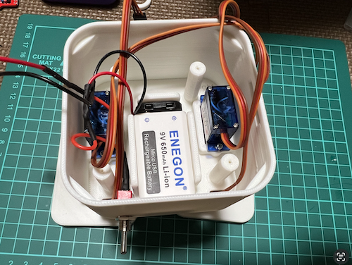
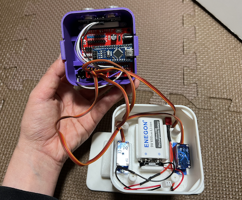
Switch and Battery Installation
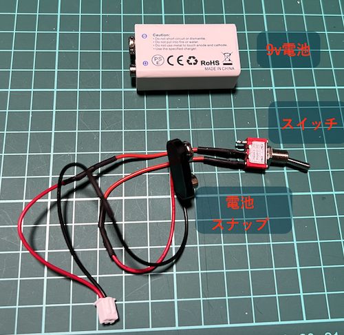
- Remove the nut from the switch and insert the switch through the body hole
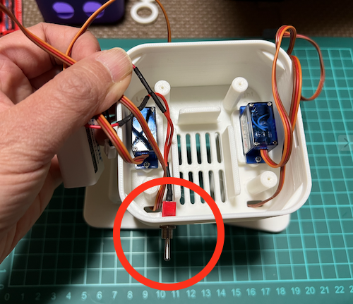
- Secure with nut from outside of body
- Connect battery snap to battery
- Insert into body, being careful not to pinch battery wires
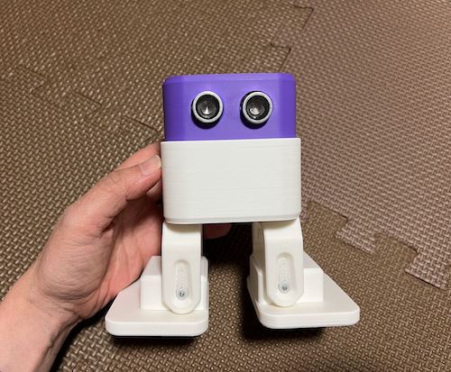
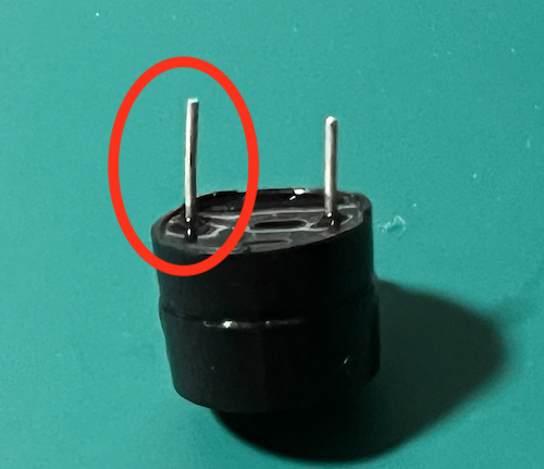
Set Distance Sensor and Buzzer
- Insert buzzer
- Insert distance sensor and screw the fixture x2
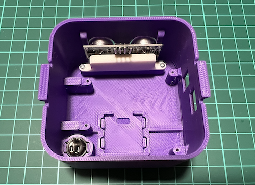
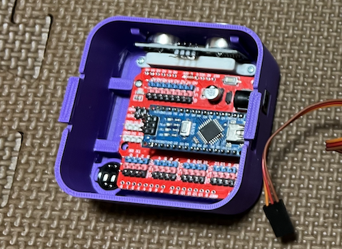
Put Microcontroller in Head
- Attach microcontroller (Arduino NANO) to expansion shield
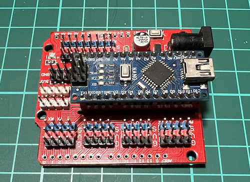
- Screw board to head x4 Pay attention to orientation and don’t bend pins when inserting
Wiring
- Wire according to wiring diagram
- Be careful about orientation to avoid short circuits!
Assembly Complete
Wiring Diagram
- Look carefully at connection diagram and pay attention to orientation.
- Be careful about orientation to avoid short circuits
| Servos (Pay attention to connector orientation) | Distance Sensor & Buzzer | Buzzer Caution (longer leg is +) |
|---|---|---|
| 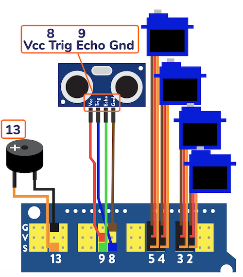 |  |
Contact
If you have any questions about the assembly, please feel free to ask our staff.