· FabLab Westharima Team · Laser Processing Machine · 7 min read
[2025 Edition] Must-See for CO₂ Laser Processing Beginners! Vector vs Raster Differences and Foolproof Data Creation Methods
Thorough explanation of CO2 laser processing basics and vector vs raster format differences for beginners. Start safe and reliable laser processing with common failure examples and recommended settings.
Everyone who has just started laser processing inevitably faces the “difference between vector and raster.” Even if you understand it verbally, it’s not uncommon to stumble when actually creating data or processing.
In this article, based on experiences I actually failed and learned from, I’ll explain not only the difference between vector and raster, but also failure examples beginners tend to make and tips for data creation using the free software Inkscape.
📌 Target Audience for This Article This article assumes CO₂ laser processing machines (hobby machines around 40W-80W). Some specifications may differ for fiber lasers or diode lasers.
📖 Terminology Definitions In this article, terms are distinguished as follows:
- Vector format / Raster format: Data storage formats (SVG, PNG, etc.)
- Vector processing / Raster processing: Processing methods in laser machines (irradiation along paths vs. scanning entire surface)
Basics of Vector and Raster Formats
Image formats (vector and raster) each have different characteristics, so you need to choose the most suitable data format for your work.
| Vector Format | Raster Format | |
|---|---|---|
| Data Structure | Points, lines, paths digitized (expressed by coordinates) | Collection of very small squares (pixels) |
| Enlargement/Reduction | Borders remain smooth even when enlarged | Outlines become jagged when enlarged |
| File Extensions | SVG, EPS, AI | PNG, JPG, GIF, BMP |
| Software | Inkscape (free), Illustrator, etc. | GIMP (free), Photoshop, etc. |
| Good for | Text, shapes, illustrations and icons, logos | Photos, images with subtle color gradations |
Differences Between Vector and Raster in Laser Processing
In laser processing machines, vector and raster have very different processing methods. You need to choose the optimal format depending on the laser processing content you desire.
| Vector Processing | Raster Processing | |
|---|---|---|
| Laser Processing | Cutting & Engraving | Engraving Only |
| Laser Head Movement | Processes by tracing indicated lines (paths) | Processes by repeating horizontal scanning in X-axis direction |
| Laser Light Output | Continuous irradiation from start to end point | Spot irradiation per pixel |
| Processing Time | Short time due to efficient movement | Takes time as entire surface is scanned |
| Suitable Work Examples | Shape cutting, text cutouts | Photo engraving, works requiring gradation or shading expression |
Understanding Laser Head Movement
To understand the difference between vector and raster, knowing laser head movement is very important.
| Vector Processing | Raster Processing | |
|---|---|---|
| Movement Method | Moves along path while continuously laser irradiating | Moves left and right while spot irradiating per pixel |
| Line Processing Image | 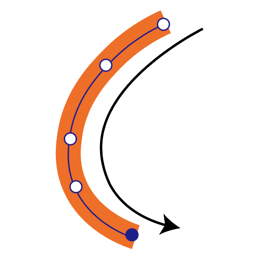 | 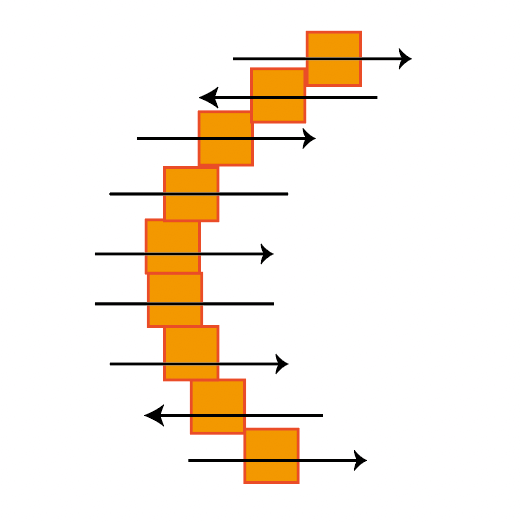 |
| Shape (Fill) Processing Image | 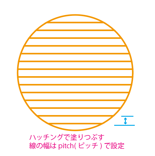 | 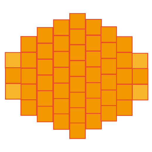 |
Vector processing moves like drawing in one stroke from path start to end point, characterized by efficiency and short processing time. Raster processing always reciprocates from left to right, scanning the entire surface, so it takes time.
Top 5 Beginner Mistakes
I’ll introduce failure examples I actually experienced or that many beginners fall into. Just knowing these can avoid many troubles.
① Thinking Changing Line Width Makes Processing Thicker [Most Important]
This was the biggest misunderstanding I made at first.
- Wrong perception: “If I make line width thicker in drawing software, laser processing will also be thicker”
- Correct understanding: In vector processing, the laser is output according to set parameters along the path (line center). Even if you change line width to change apparent thickness, actual processing width (kerf: cutting width) doesn’t change. Processing width is determined by laser output, speed, focus, and material.
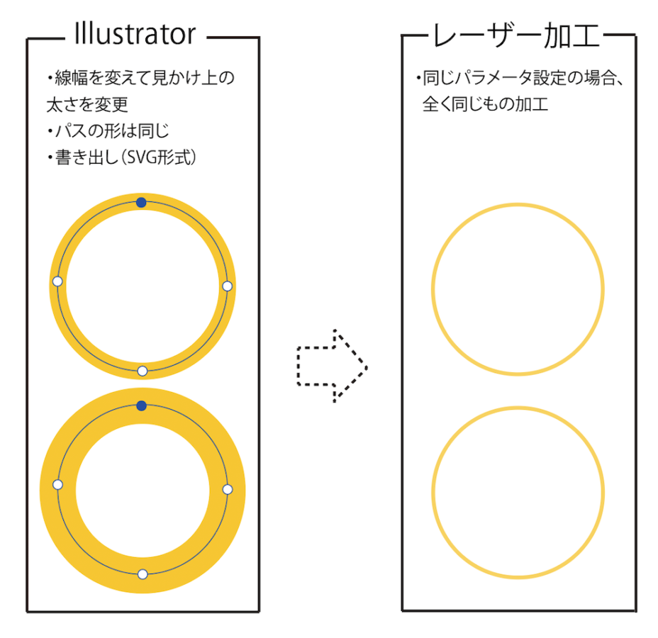
- Solution: To create thick lines, arrange multiple paths in parallel or outline them. Adjust with laser output power or speed.
② Overlooking Duplicate Paths (Double Lines) [Dangerous]
If multiple paths overlap in the same location, the laser processes the same spot twice or more. This causes material to scorch or burn, and in the worst case, there’s a fire risk.
Confirmation method (Inkscape): Select all (Ctrl + A) → View → Display Mode → Outline (Ctrl + 5) → Visually check for overlapping paths
③ Lines Too Thin or Spacing Too Narrow
Reference values (guideline for typical 40W-80W CO₂ lasers):
- Minimum line width: 0.3mm or more (laser beam width is about 0.3mm)
- Minimum spacing: 0.7mm or more recommended
- Material vaporization: About 0.2mm width vaporizes
⚠ Important: These numbers vary greatly depending on machine model, output, material, and focusing lens. Always confirm with test cuts.
Even if you draw 1mm spacing lines in data, actual processing may result in about 0.8mm spacing (0.2mm vaporizes).
④ Forgetting to Convert Text to Paths (Outline)
If you pass data without converting text to paths, if that font doesn’t exist on the laser machine side, it will be replaced with a different font or the character shapes will collapse.
Path conversion procedure in Inkscape: Select text → Path → Object to Path (Shift + Ctrl + C)
Caution: Once converted to paths, text cannot be edited, so always make a backup. Be sure to check for typos before converting to paths.
⑤ Failure from Mixing Raster and Vector
- Cutting requires vector paths. Image lines are raster data so cannot be cut. When mixing, clearly separate each layer or color.
Free Data Creation Software
To create data for laser processing, dedicated software is necessary. Below, I’ll introduce representative free software.
| Software Name | Type | Suitable for Laser Processing | Uses & Points |
|---|---|---|---|
| Inkscape | Vector Graphics | ◎ (Most suitable) | - Accurately specify “cut lines” and “engraving lines” in SVG format - Easy to specify processing conditions by line thickness and color - Direct support by many laser machines (Glowforge, xTool, FLUX, etc.) - Main tool for laser data creation |
| GIMP | Raster (Bitmap) Image Editing | △ (Mainly for engraving data) | - Create engraving processing images by converting photos and illustrations to grayscale - Not suitable for handling cut lines (vector needed) - Use as auxiliary for creating engraving and marking data |
| Krita | Paint & Illustration Creation (Raster-based) | △ (Art-type engraving data) | - Hand-drawn style illustration and texture creation - Weak vector data output - Suitable for creating art-oriented engraving materials |
Selection Points:
- Need cutting → Inkscape (essential)
- Photo engraving → GIMP or Krita
- Hand-drawn style design → Krita
All support Japanese and have many online tutorials, making them easy to learn even for beginners.
Points for Data Creation in Inkscape
From here, I’ll explain specific data creation methods using Inkscape.
Basic Settings
Lines for cutting:
- Line width: 0.1-0.3mm
- Color: RGB red (R: 255, G: 0, B: 0)
- Fill: none
For engraving (vector):
- Fill: RGB black (R: 0, G: 0, B: 0)
- Line: none
💡 About Color Settings Many laser machines can set different parameters (output, speed) for each color. Generally, red is for cutting, blue or green for engraving, black for raster engraving, but support varies by model. Check your machine’s manual.
Essential Operations
| Operation | Procedure | Shortcut |
|---|---|---|
| Convert Text to Path | Path → Object to Path | Shift + Ctrl + C |
| Set Line Width | Object → Fill/Stroke → “Stroke Style” tab → Set width to 0.1-0.3mm | Shift + Ctrl + F (Dialog) |
| Check Duplicate Paths | View → Display Mode → Outline | Ctrl + 5 |
| Save | File → Save As → Select “Optimized SVG (*.svg)“ | None |
Data Creation Checklist
- Is all text converted to paths
- Are cut lines 0.1-0.3mm line width
- Are there no duplicate paths (check with outline display)
- Is spacing between lines 0.7mm or more
- Are cut paths and engraving paths color-coded
- Is it saved in SVG format
Recommended Value Table
| Item | Recommended Value (Guideline) | Reason |
|---|---|---|
| Minimum line width | 0.3mm or more | Corresponds to laser beam width |
| Minimum spacing | 0.7mm or more | Considers heat-induced vaporization |
| Text size (cutout) | 10mm or more | Too fine will collapse |
| Text size (engraving) | 1-3mm | Vector is clear |
| Cut line color | RGB (255, 0, 0) | Visibility, unified settings |
| Cut line width | 0.1-0.3mm | Recommended by many machines |
⚠ Caution: The above numbers are guidelines for typical CO₂ lasers (40W-80W). In actual processing, they vary greatly depending on machine model, material, and parameter settings, so always confirm with test cuts.
Summary
What You Learned in This Article
- Difference between vector and raster: From data structure to processing methods
- 5 major beginner failures: Line width misunderstanding, duplicate paths, lines too thin, forgetting path conversion, format mixing
- Laser head movement: Vector is one-stroke drawing, raster is reciprocating scan
- Data creation method in Inkscape: Recommended values, checklist, color-coding settings
What I Learned from Actual Processing
- Even understanding verbally or in diagrams, actual processing reveals new discoveries
- Learning from failures is very common
- Small attention during data creation greatly affects processing results
- By imagining laser head movement, you can choose appropriate data formats
- Even free Inkscape can create professional quality data
Next Steps
- Download Inkscape and actually try using it
- Try creating simple data (squares, circles, etc.)
- Understand parameters for each material with test cuts
- Challenge more complex designs
Laser processing is a continuous trial and error, but once you master the basics, you’ll definitely improve. With the free tool Inkscape, anyone can start creating laser processing data today.
![[Free & Commercial Use OK] Illustration Material Collection Sites for Business Use](/_astro/656d0ea2b8478d70c95a8f897ecc44e3.Dunk5eRy.png)
!['[2025 Edition] Complete Soldering Guide for Electronics | Basics and Tips Even Beginners Won't Fail'](/_astro/soldering_guide_eyecatch.DghrOCBg.png)